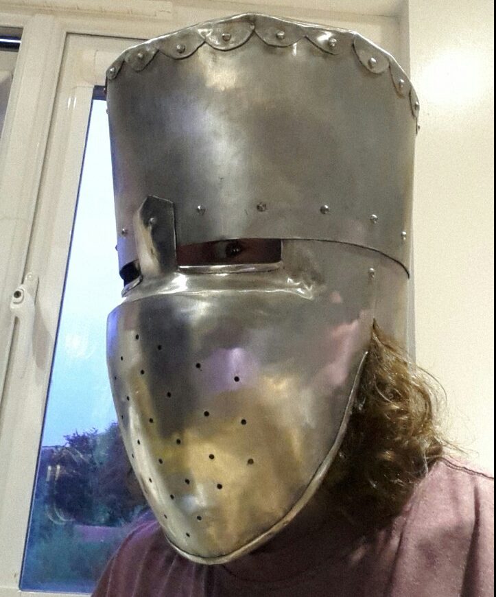
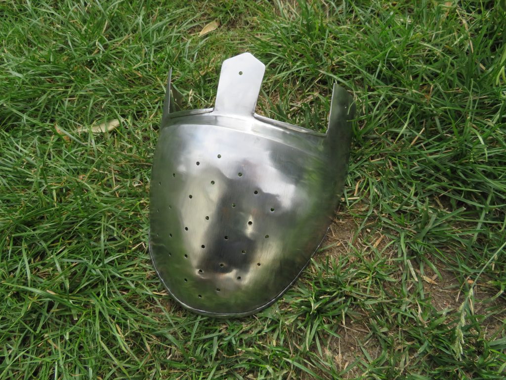
An enclosed helmet is the predecessor to the well known great helm that was used in the late 12th and early 13th century, which has a flat top, complete coverage at the front with a face plate and partial coverage around the sides and back. There are relatively few artifacts or depictions showing this form of helmet (at least freely available on the internet, that is) so there was a fair bit of interpretation as to the exact form and construction on my part for this. This was informed from some of the depictions in illuminations and also from other modern reproductions.
Planning and Pattern
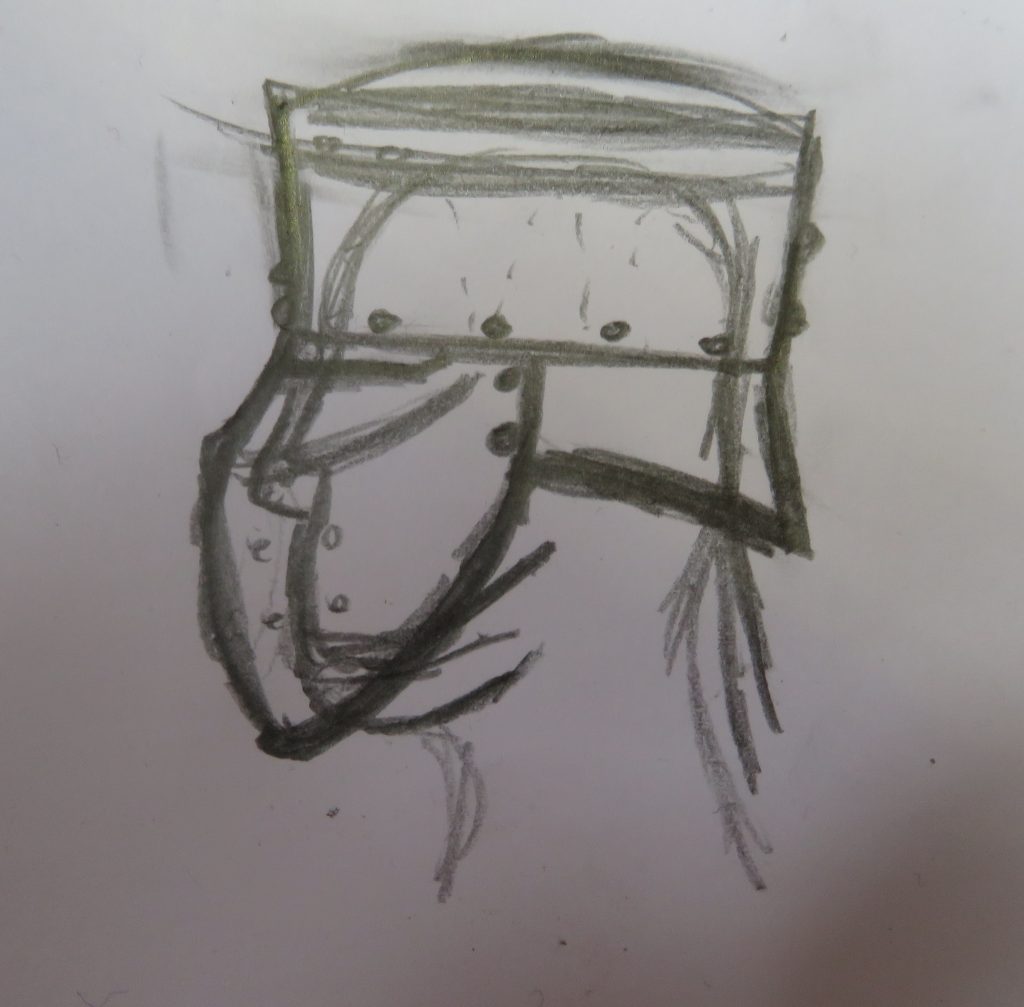
I began by sketching A plan for how I wanted the helmet to look and fit on a head. I planned a construction from four pieces: A face plate; a smaller back-of-head-plate; A long plate around the top of the head; and a circular top plate.
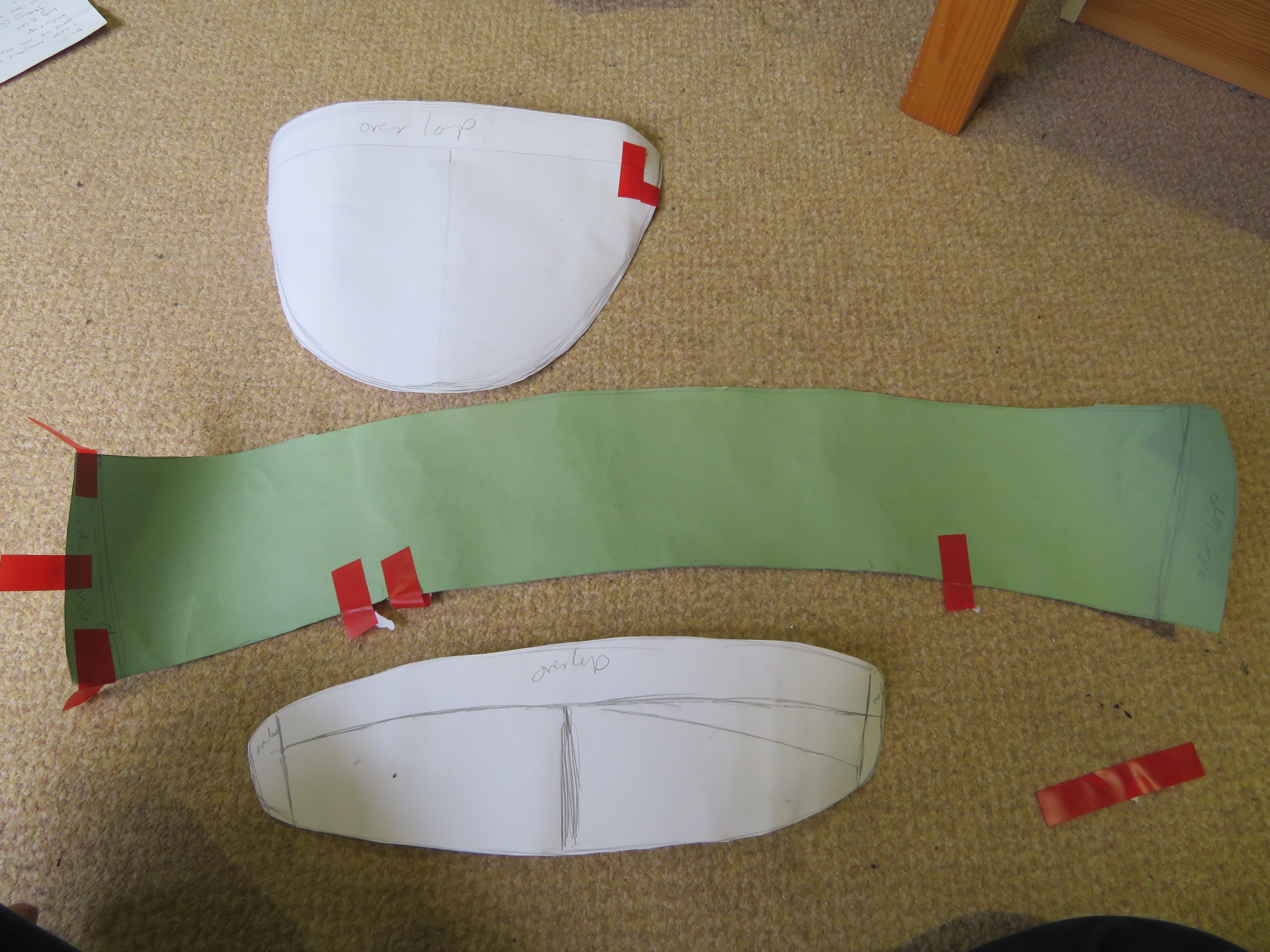
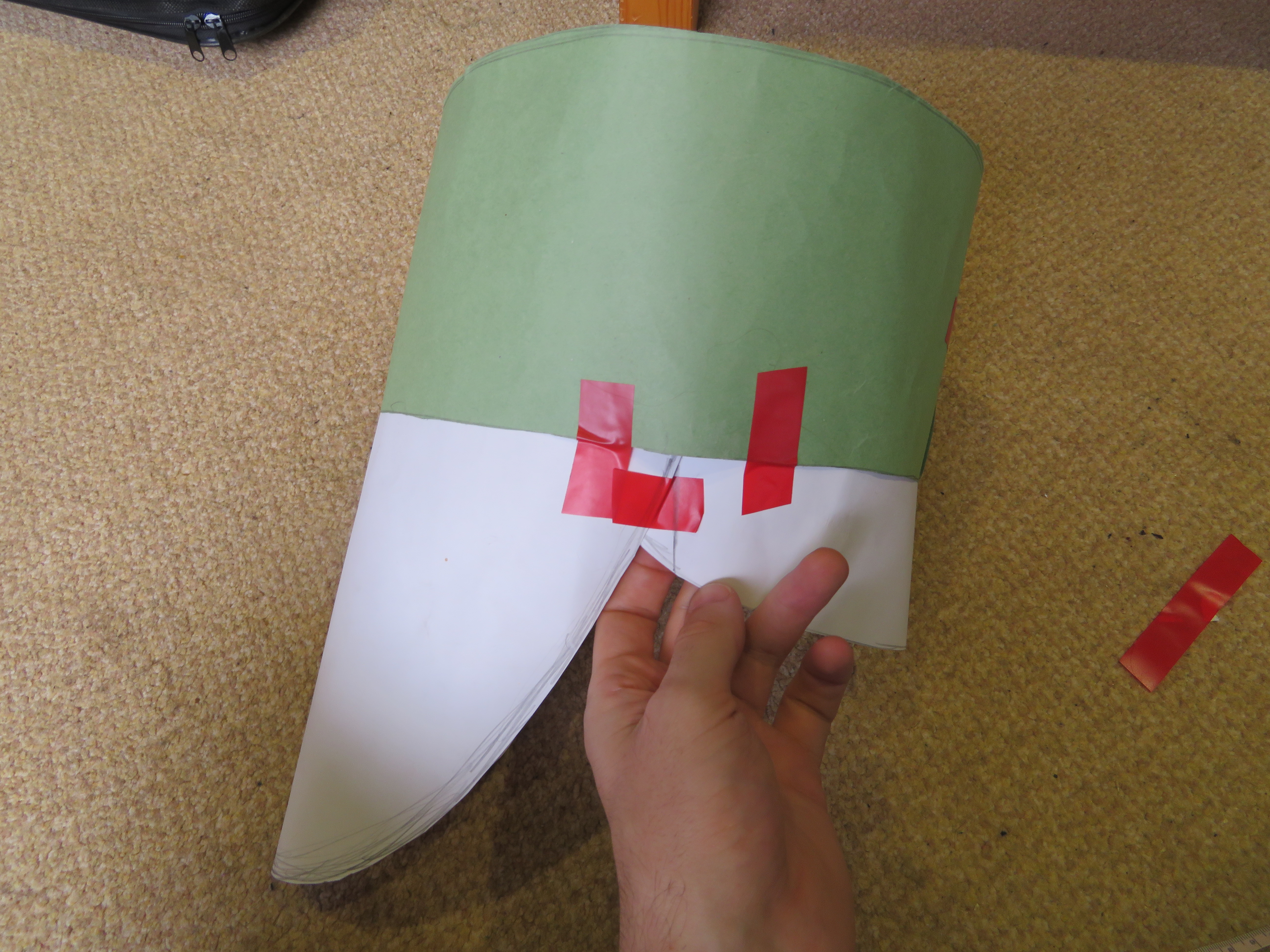
I then planned out the pattern for each piece. I started by taking measurements from my head with a fabric measuring tape. I made each piece over sized as it is very easy to cut them down later, but much harder to make them bigger.
I worked out the pattern for the upper plate using an online calculator for the net of a conic frustum, which gives it the larger diameter at the top than the bottom. I made a few versions of this pattern with different parameters and tried them on to determine the right proportions. I largely eye-balled the shape for the front and back plates patterns based on the upper plate pattern I selected and a few key measurements from my head. I didn’t make a pattern for the top plate as I would need to make that to fit one I had already shaped the rest of the helmet.
Cutting and Preparing the Pieces
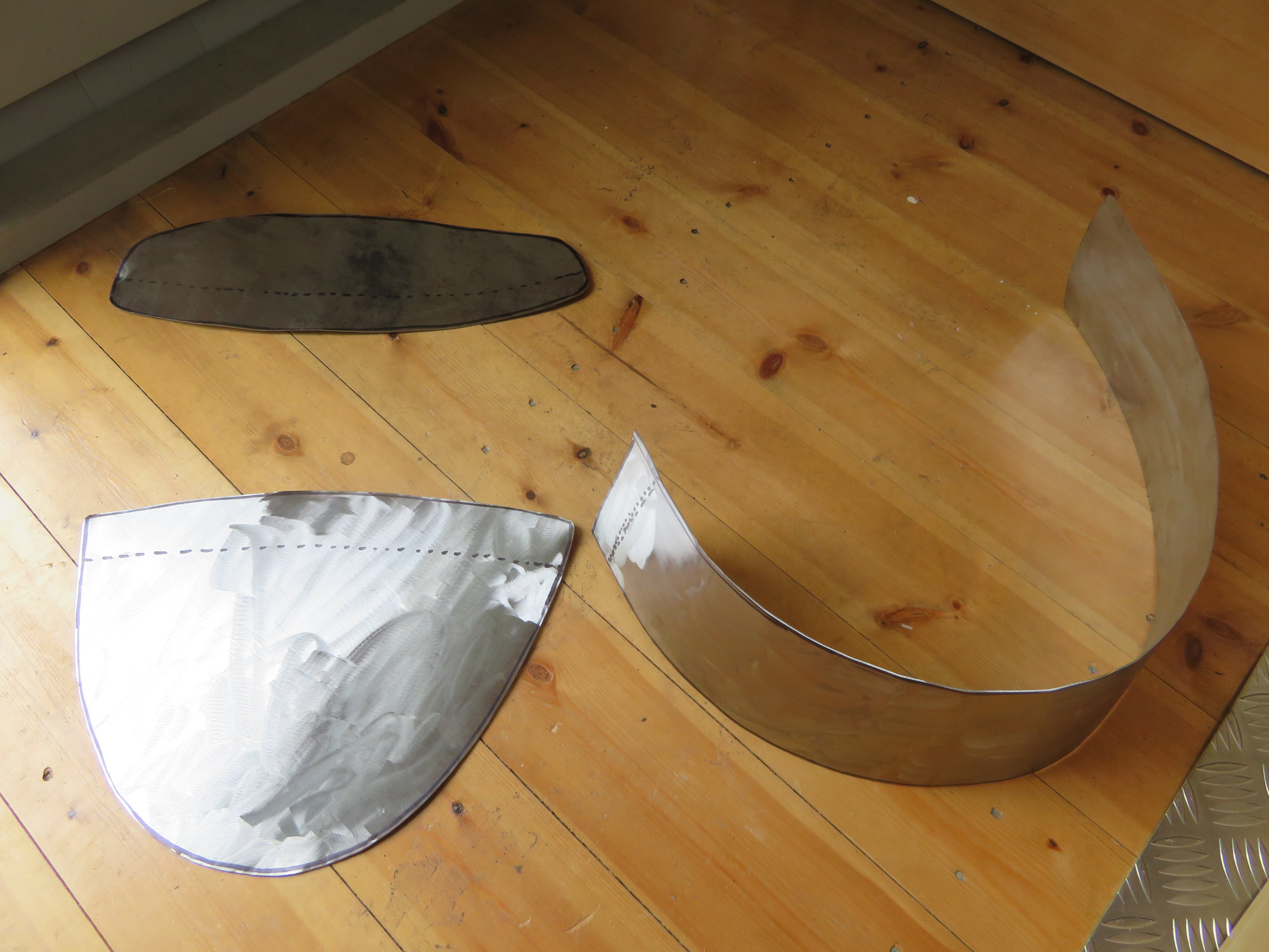
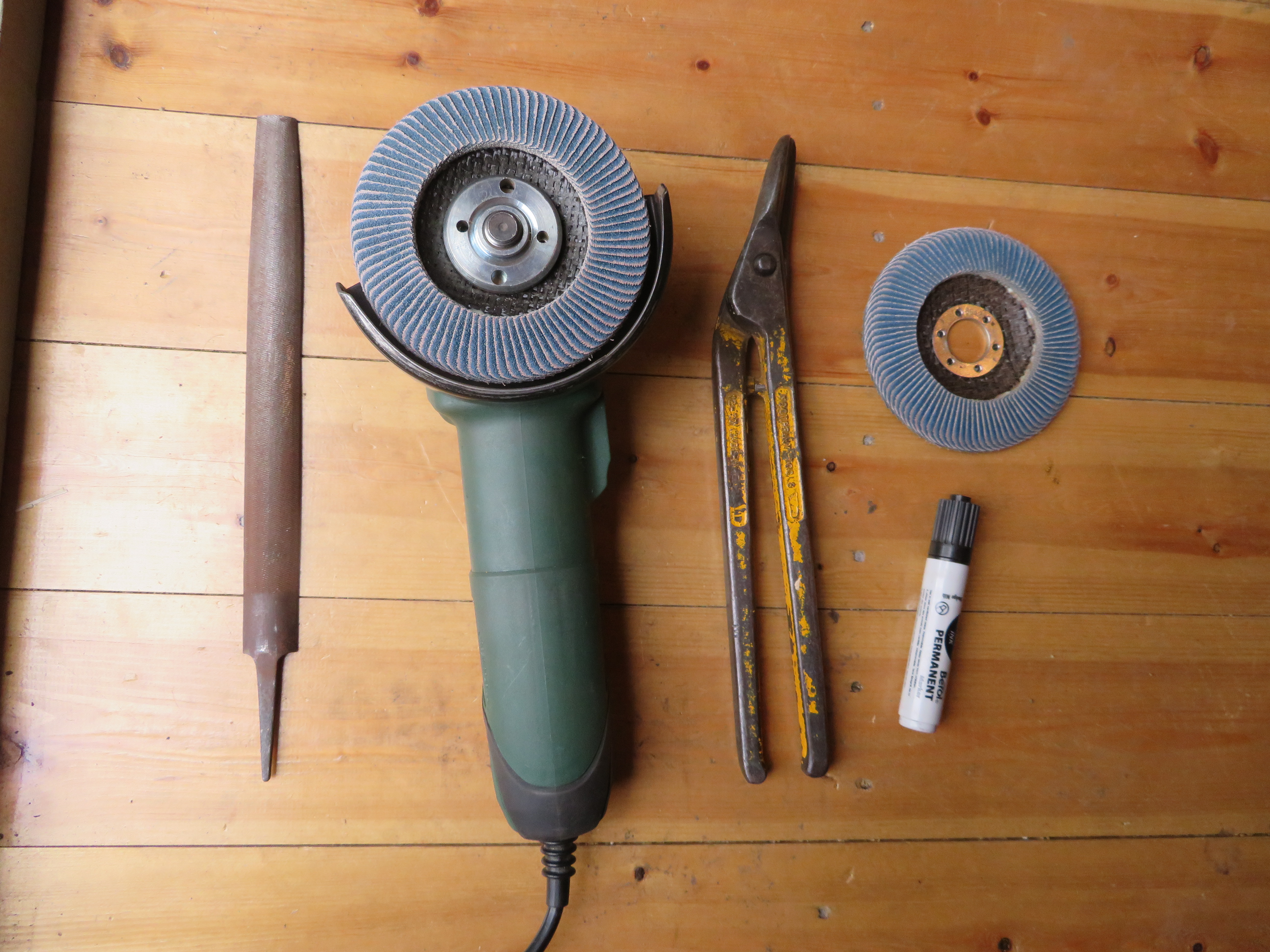
I marked up the parts onto steel sheet from the pattern and cut them out using hand shears. These can be somewhat tricky to use, mine definitely have a bit of a knack to them and I remember I used to struggle with cutting larger pieces out. I have found that it it much easier to cut out the pieces with lots to spare around the edges initially and then go back and cut closer to the line on a second pass. This means you aren’t trying to make accurate cuts and sharp turns while there is a large amount of material, which is harder as the shears work by bending the off cut away, which is harder when there is more material to bend.
I then de-burred the edges and cleaned off the surface rust with 60 and 80 grit flap disks on the angle grinder (I wouldn’t recommend flap disks for this as I have found they seem to leave a surface finish that makes things more difficult when it comes to polishing). Finally I remarked the areas where plates were going to overlap.
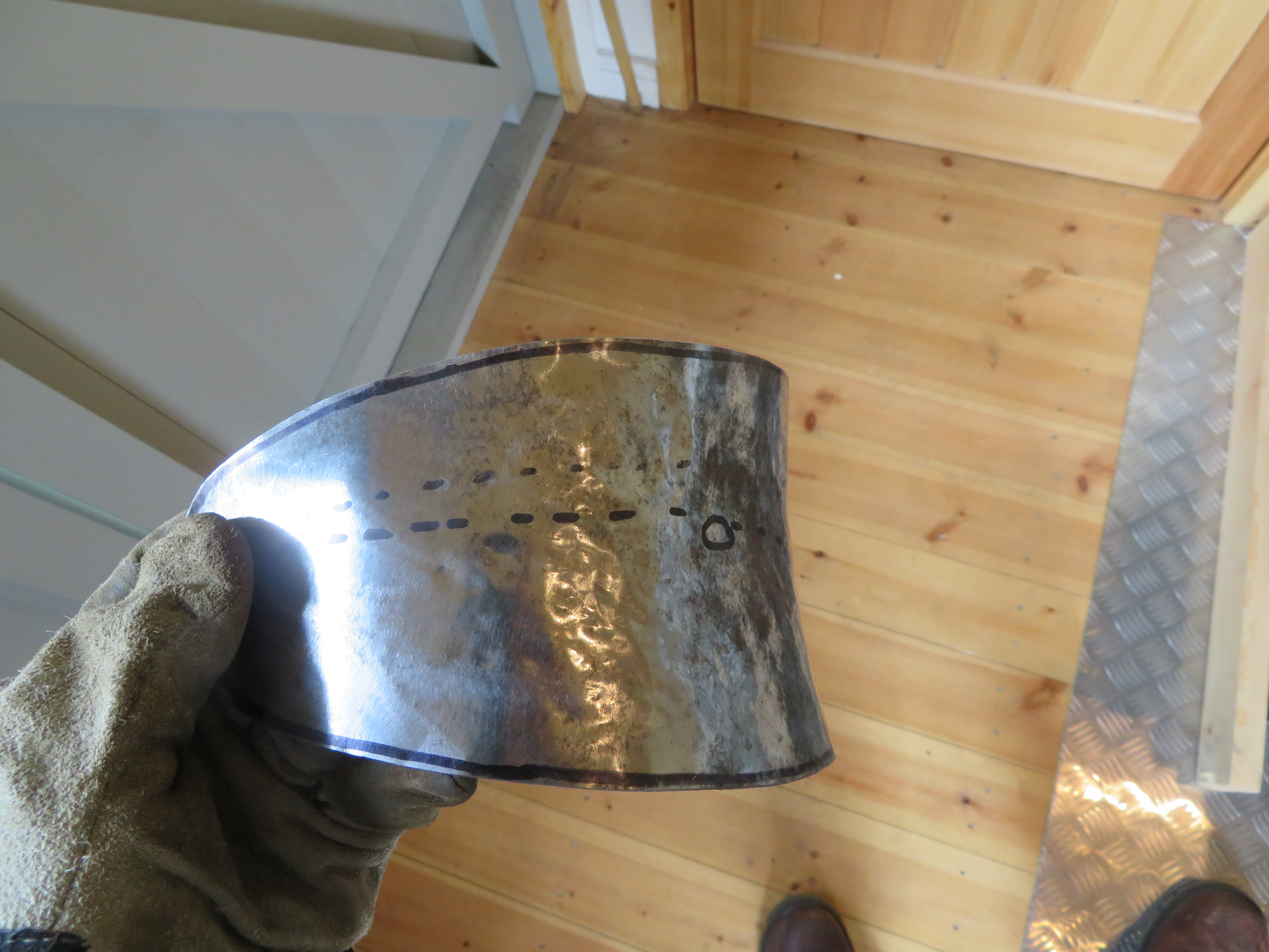
Shaping the Front, Back and Upper Plates
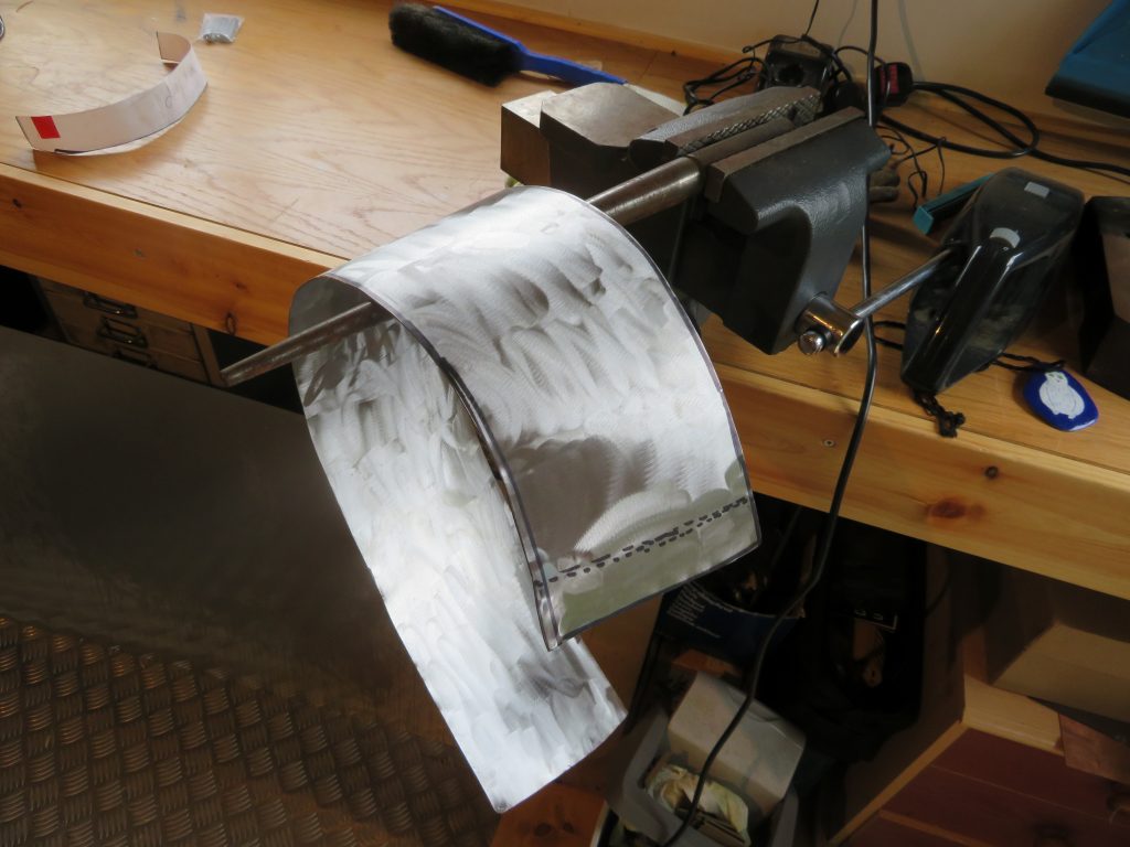
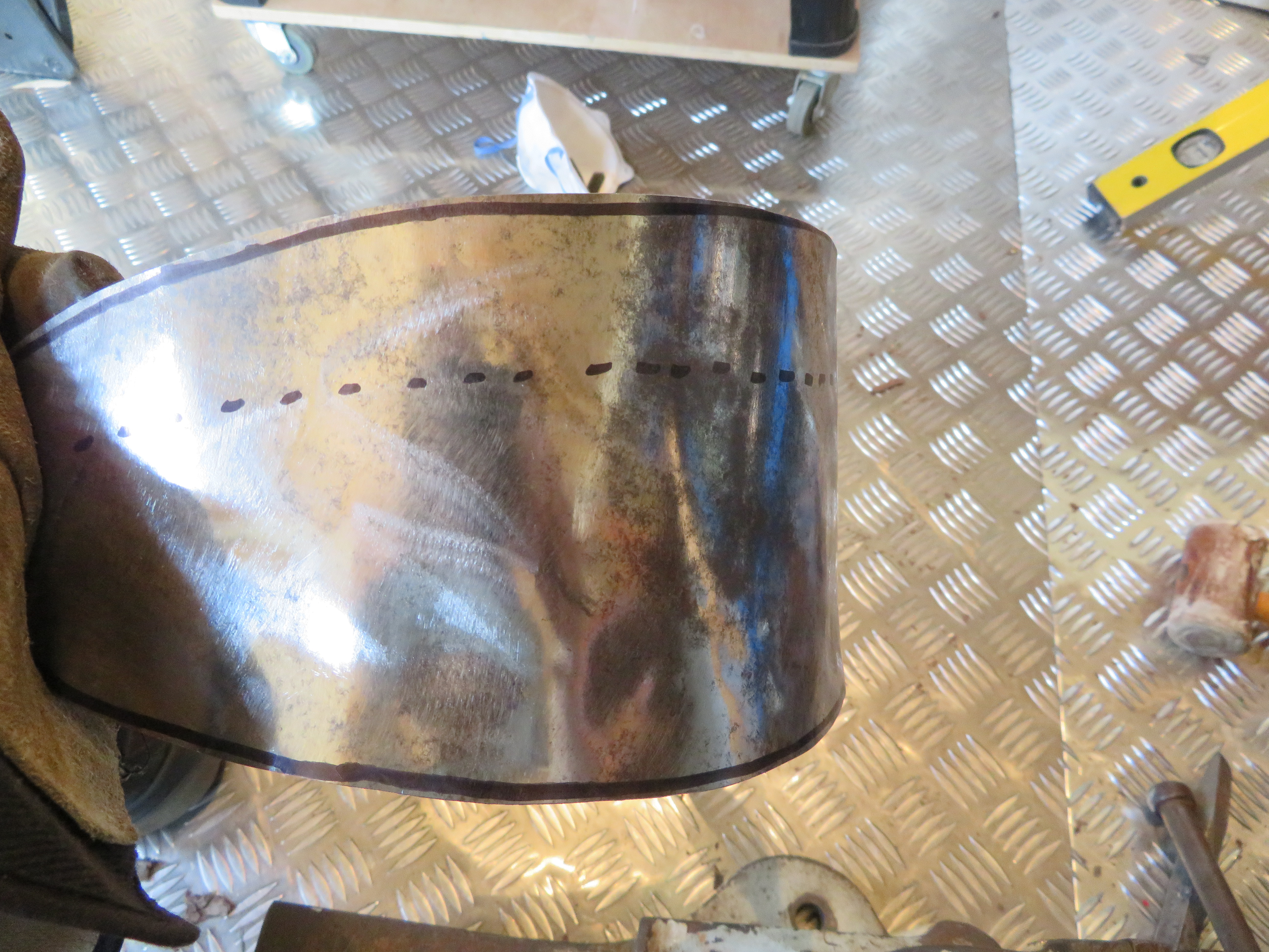
The upper plane was simple to shape as it only curves in one plane. I bent it by hand over a ring mandrel held in a vice, which was standing in for the horn of an anvil. I continually moved it and put small amounts of bend in at each point to give a smooth curve. At each end it becomes difficult to bend by hand as the leverage gets smaller and I needed to use a leather mallet. This is where I really missed having an anvil as the long lever action of the ring mandrel in the vice meant I could only get a few hammer blows in before I had displaced the mandrel and had to reset it in the vice. Once the part was shaped I punched 3 holes on the overlaps and temporarily secured them with bolts.

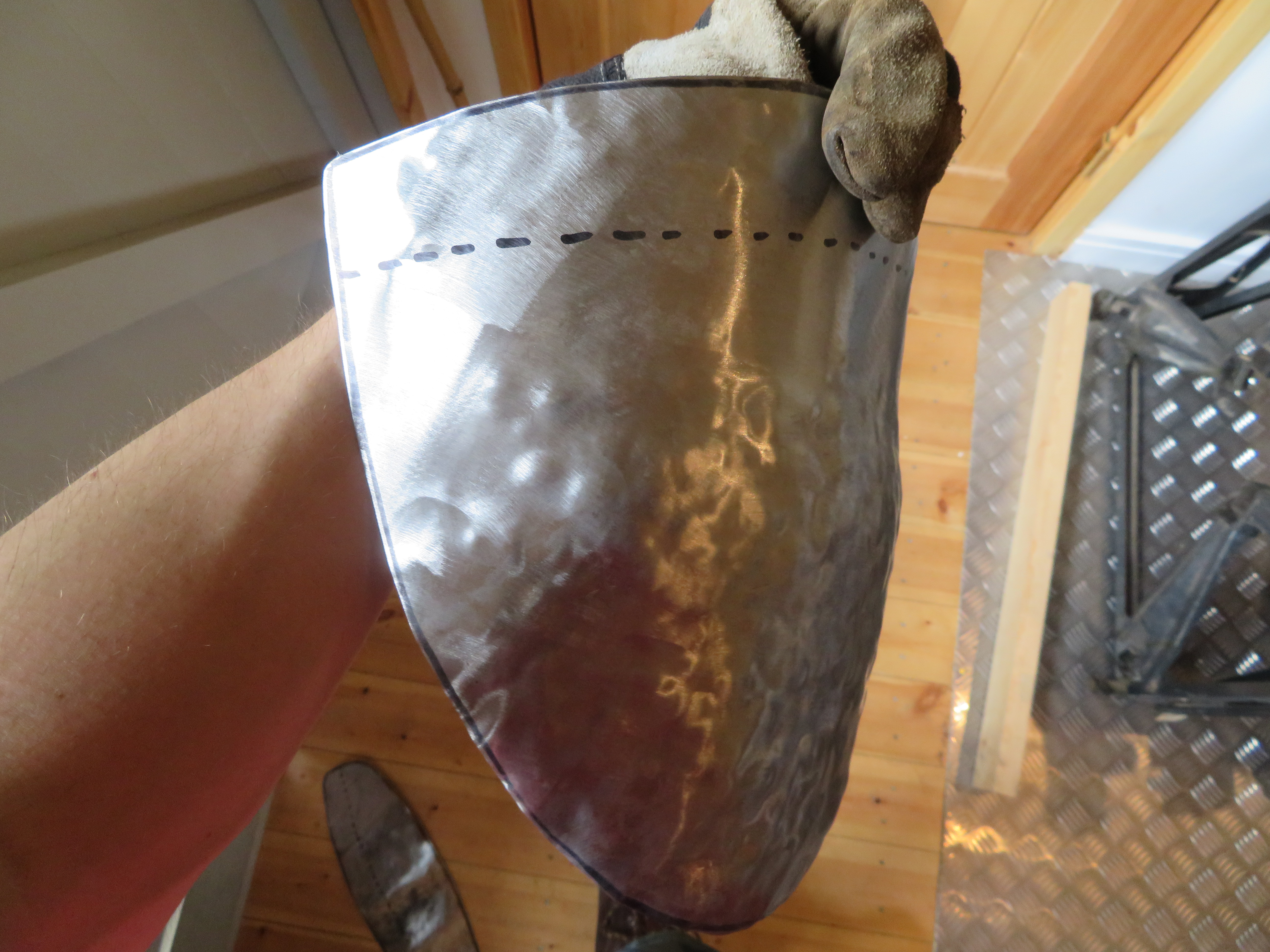


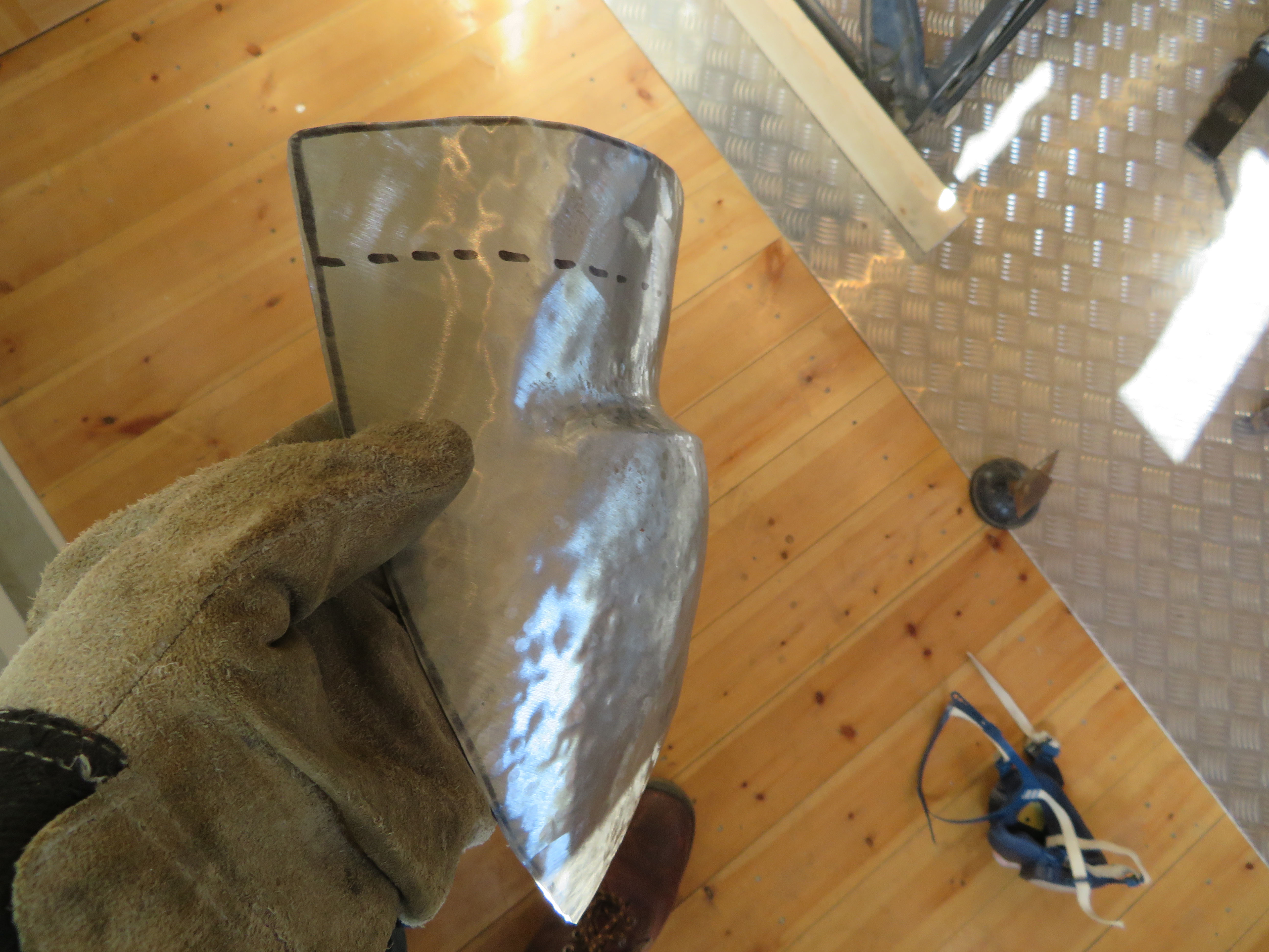
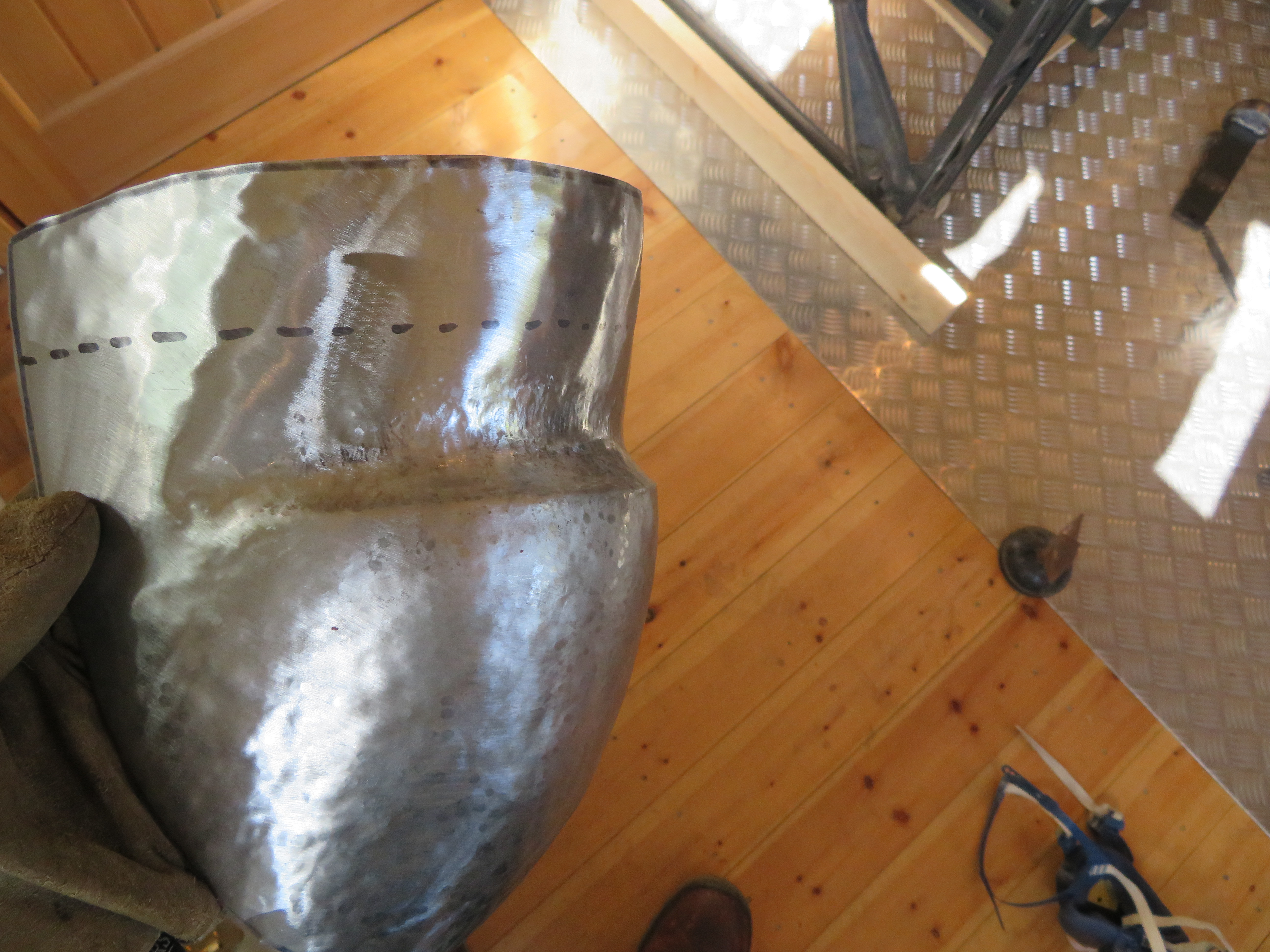
I shaped the front plate with a combination of dishing into a stump and raising over a mushroom stake to make the curvature for the fave plate. I then added a crease towards the top over a blunted chisel. Finally, I plannished the surface to remove the hammer marks.
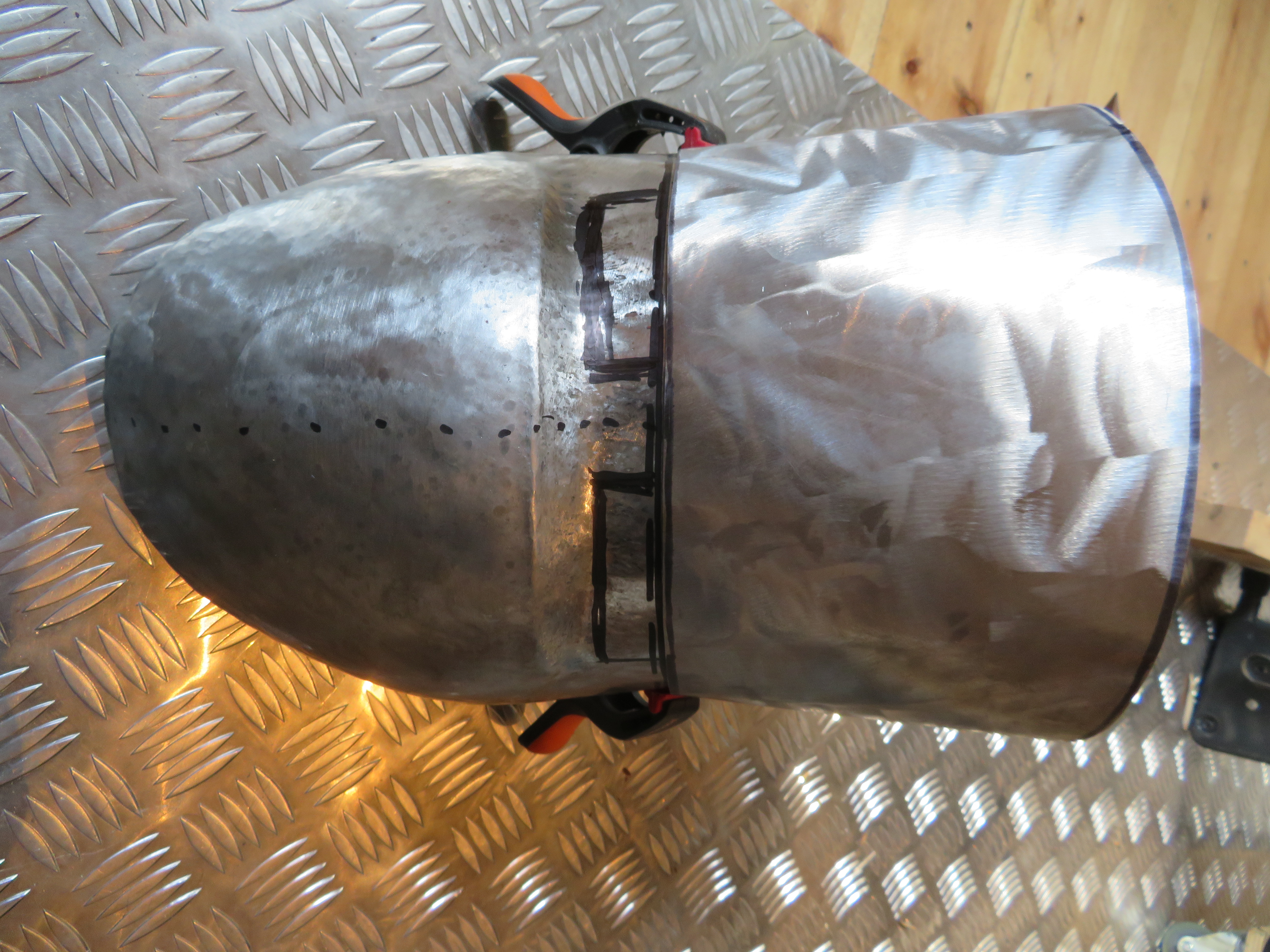


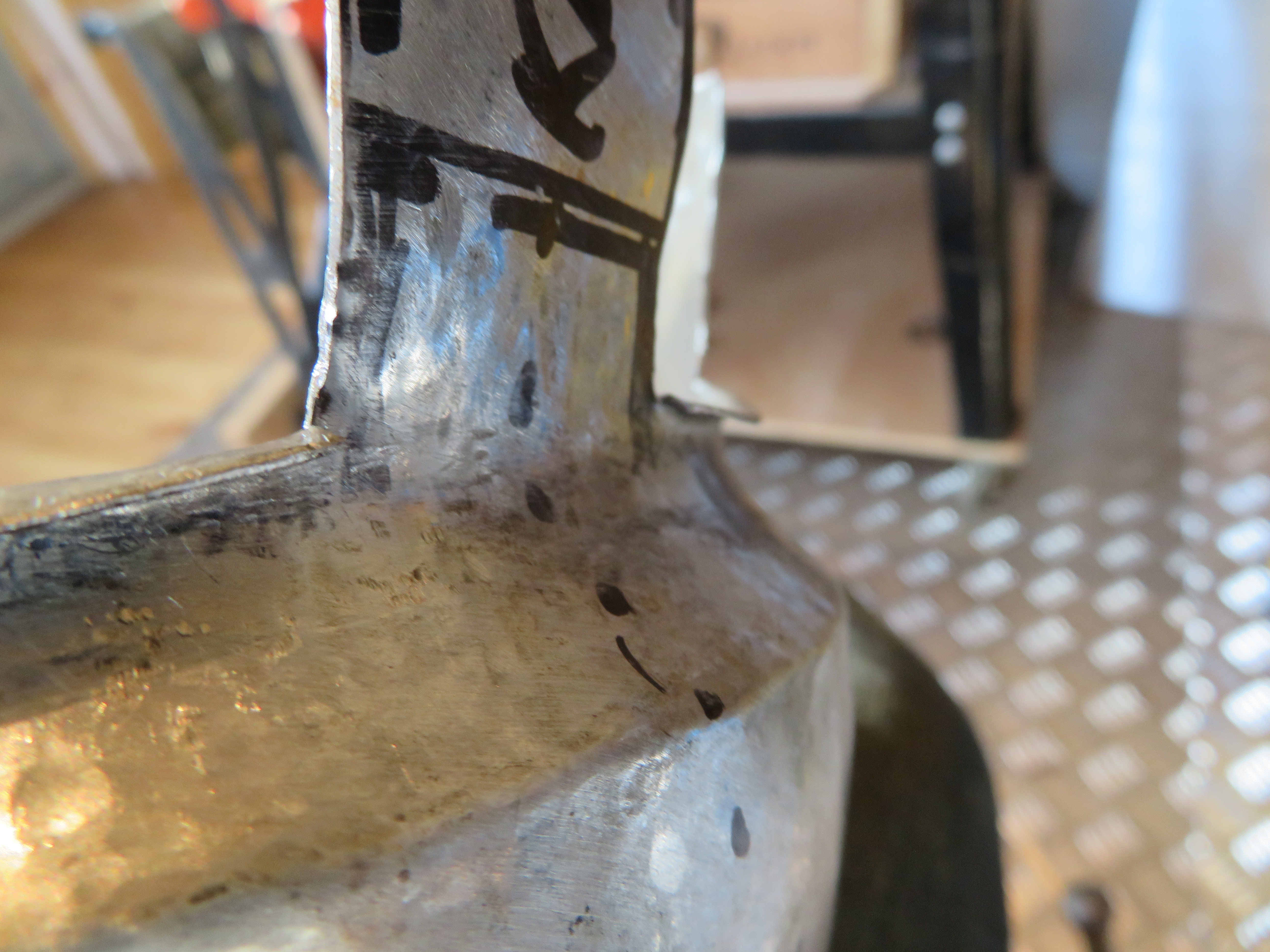
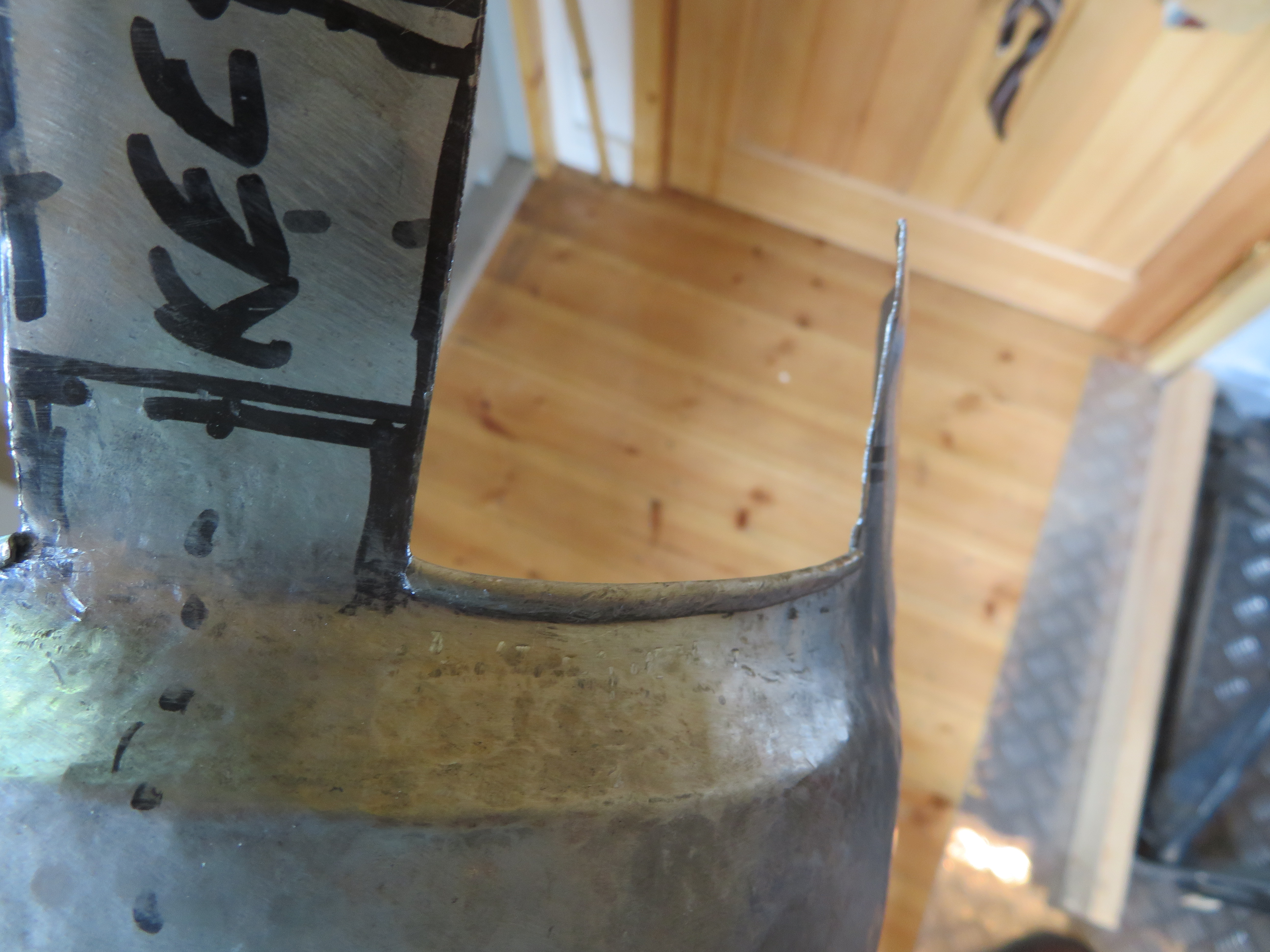

I then married up the face plate and the upper plate to work out where they should overlap and marked up where the eye holes should go. In marking up the eye holes I had to account for the fact that I would roll over the bottom of each, which would make the holes larger. I cut out the eye holes using a combination of hand shears, a slitting disk on a dremel, and hand files.


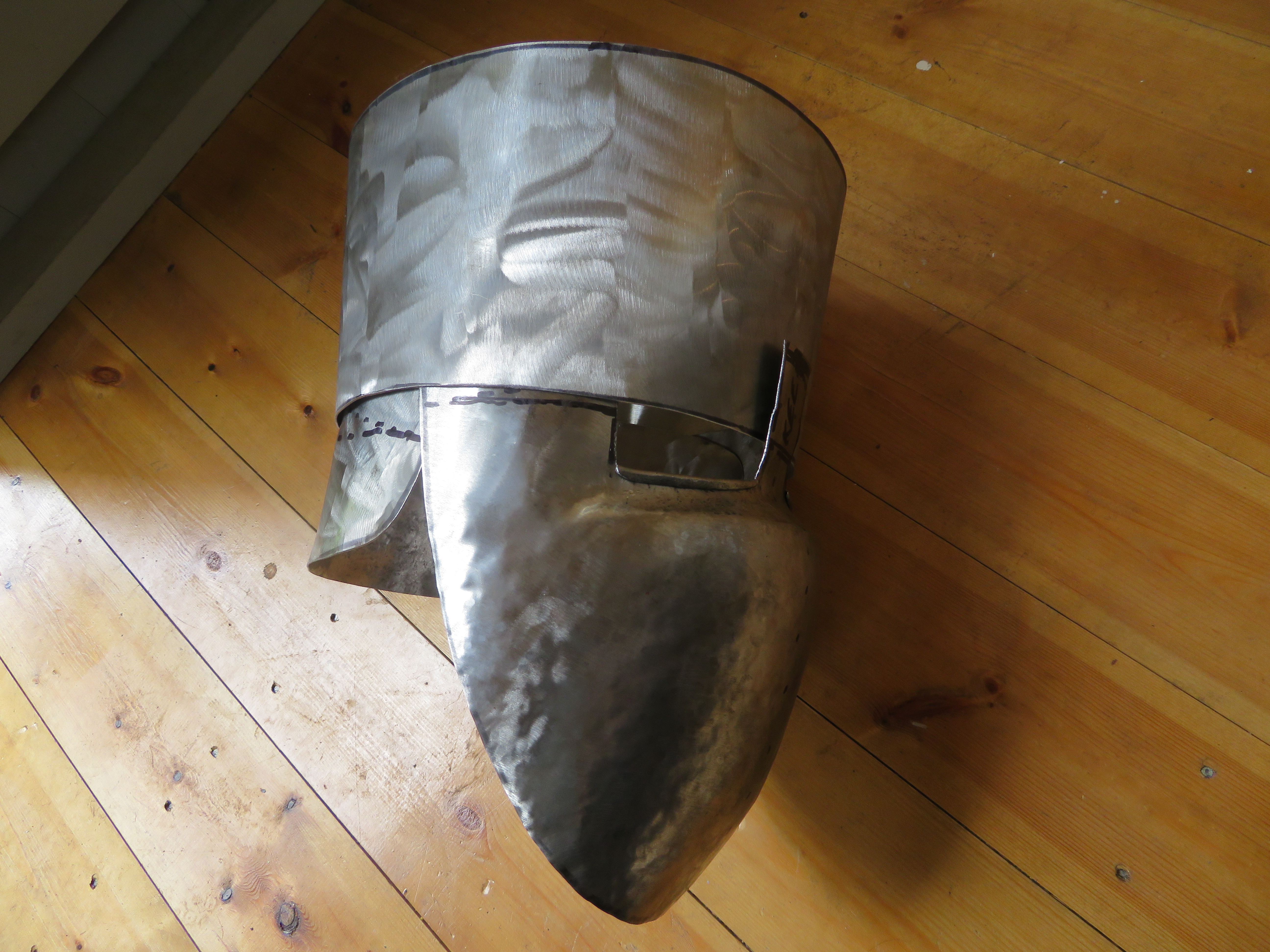
Shaping the back plate was somewhat more difficult that the first two as I wanted it to flare out meaning it was curving in opposing directions on each axis, which is going against how the metal wants to move.


Once these plates were shaped I punched holes around the overlaps and temporarily secured them with bolts.
The Top
By far the most challenging part of this was shaping the top, which took me three attempts. The difficulty is that to join the top to the upper plate there needs to be a bend of more than 90 degrees all the way around the rim, which is creates a lot of excess material. Due to general frustration throughout this process I forgot to take many pictures.
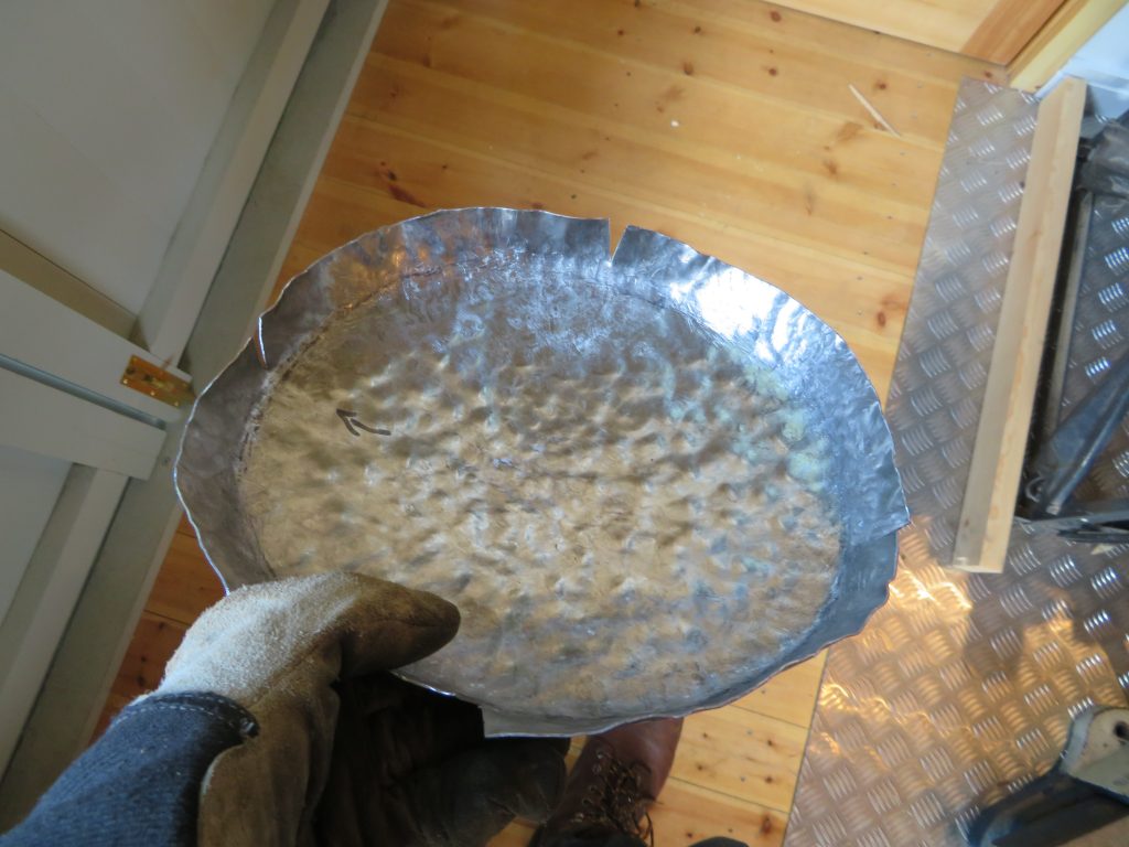
In my first attempt I started by using the shape from the already assembled parts to mark out the top plate. I thought that adding some curvature to the top would make adding the bend around the edge easier as it would no longer be need to be such a large angle. This was not the case as it meant the whole piece started to warp making lining it up with the upper plate more difficult. I had initially hoped to have a solid rim all the way around but this was quickly proved not to be feasible so I cut four slits around the rim to remove some of the bulk and make bending it easier.
After a while working on this I decided I wasn’t going to be able to make it fit and to start with a fresh piece.
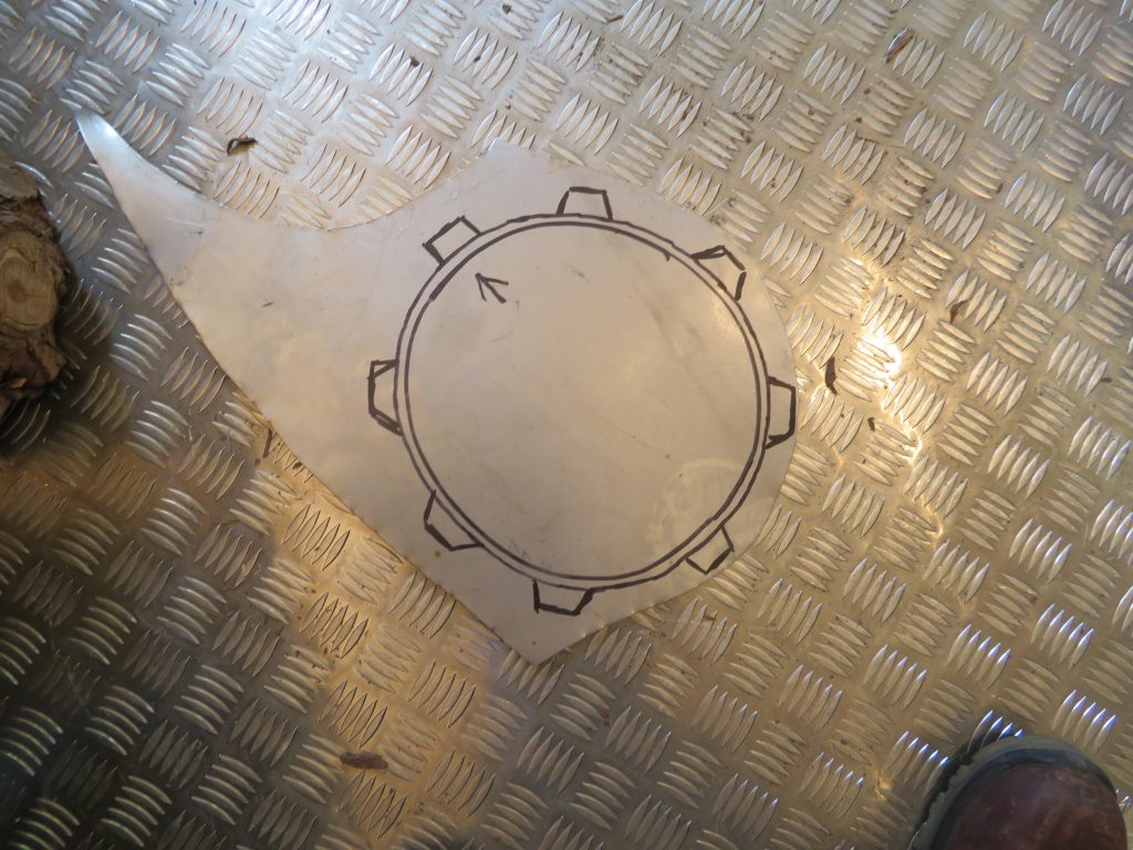
My plan for the second attempt was for the top to fit inside the upper, rather than outside, which was the plan for the last version, and to leave the top flat while I made the bend around the edge, which was only going to be a small amount of material with tabs around the circumference.
The main flaw in this attempt was the idea for the top to fit inside the upper plate as it quickly became obvious that this was going to leave a significant air gap.
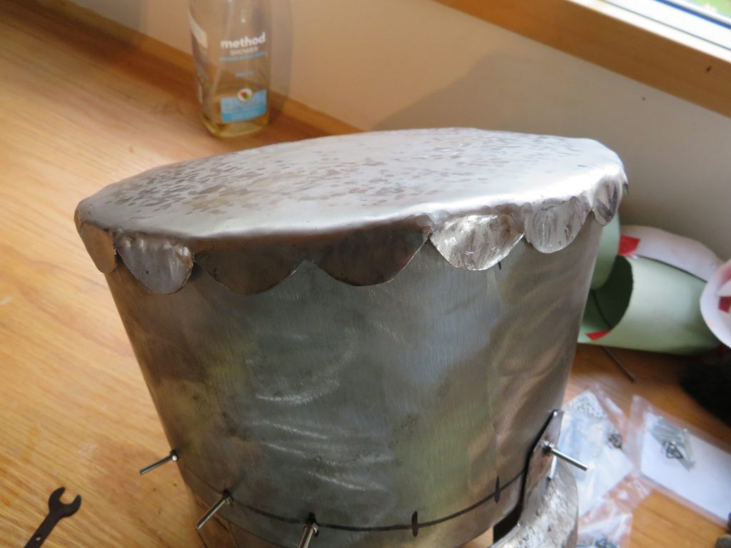
In the third attempt I decided to return to having the top fit on the outside and to have tabs all the way around. This proved to be much more successful and, once I had bent all the tabs mostly over I added a slight curvature to to top.
Finishing
I then polished up each plate going through a successively finer grits of sandpaper followed by polishing compound on polishing wheel. To protect the inside from rusting I painted the inside of each plate with black paint.
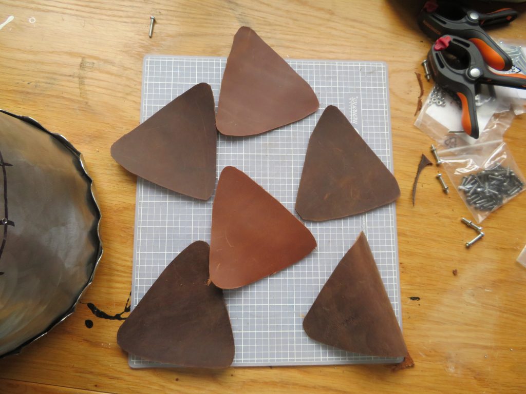
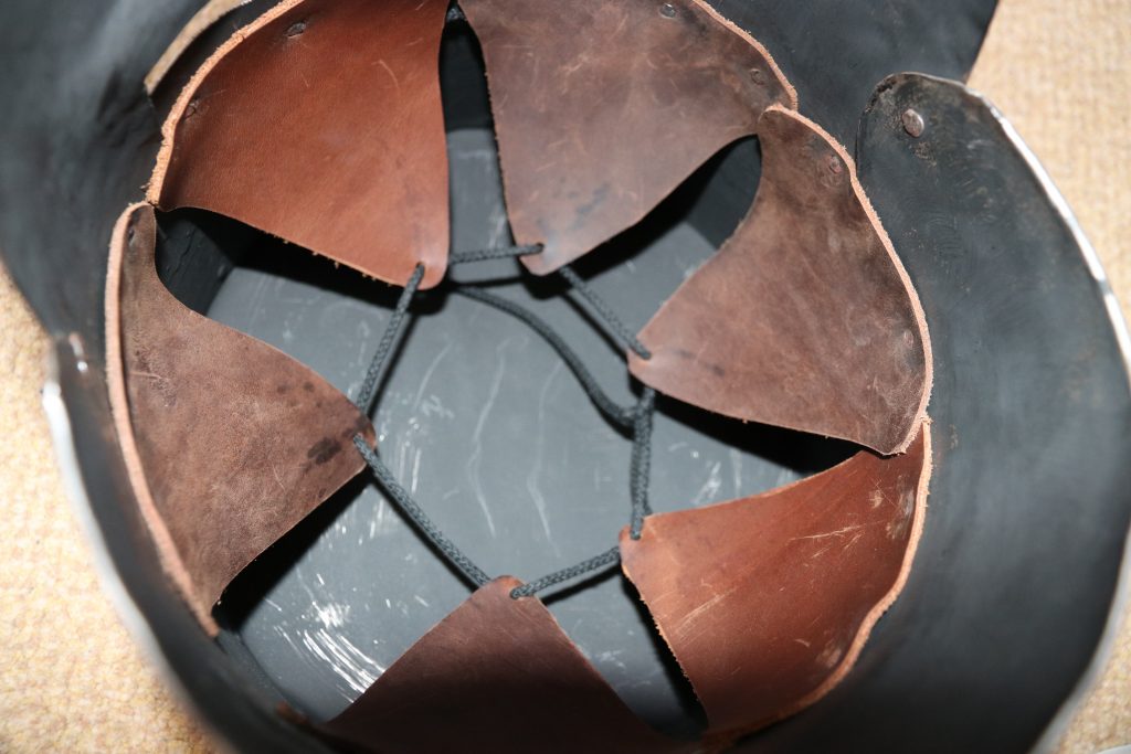
Finally I riveted all the plates together. The rivets around the brow band also held the suspension system in, which I made simply from triangles of leather each with an edge riveted to the helmet and then the remaining corners of each all loosely tied together. This system means that the metal of the helmet is not resting on your head, which would mean any impact would just be directly transferred, very similar to the suspension you find in modern hard hats. I am not sure this system of leather riveted directly to the helmet is particularly historical, from what I have seen helmet liners would more usually be textile and would be sewn to the helmet or to a second strip of leather that is itself riveted to the helmet. These systems allow the liner to be more easily replaced without having to grind out and replace a lot of rivets. Knyght Errant has a good video on the helmet suspension systems for those who are interested.